The technical objectives of the project are
• Identification of regions on the Next Generation Civil Tilt Rotor Configuration that could benefit from flow control devices
• Perform CFD simulations using ZNMF devices and investigate the parameters that have the largest influence on the quantities of interest.
• Perform a multi objective optimization study to optimize the location and parameters of the ZNMF devices
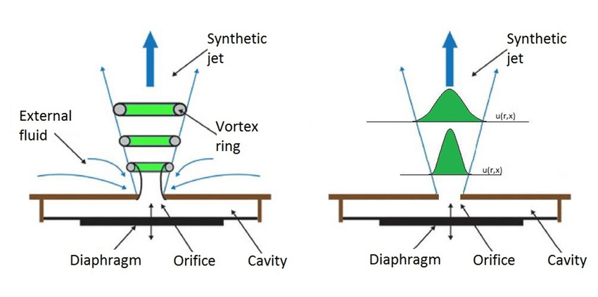
Synthetic jet: instantaneous (left) time-averaged (right)
Scientific Figure on ResearchGate. Available from: https://www.researchgate.net/figure/Synthetic-jet-a-instantaneous-b-time-averaged_fig1_310437397 [accessed 9 Nov, 2020]
About ZNMF devices
The first Zero-Net-Mass-Flux jet device was mentioned by Ingard and Labate (U. Ingard, S. Labate, Acoustic circulation effects and the nonlinear impedance of orifices, J Acoust Soc Am, 1950, 22(2): 211-218) in 1950, they used standing waves in an acoustically driven circular tube to induce an oscillating velocity field in the vicinity of an orifice end-plate and observed the formation of the ZNMF jet from opposing trains of vortex rings on both sides of the orifice.
The ZNMF jet is usually produced by a sinusoidal oscillating membrane or piston to alternatingly force fluid through an orifice into the external flow field and entrain fluid back. During the blowing stroke, the ejected fluid separates at the sharp edges of the orifice and rolls up to form a vortex pair or ring (2D with slot orifice and 3D with circular orifice, respectively). When the membrane begins its suction stroke, the vortex pair or ring is quite far from the orifice and keeps on propagating away due to its self-induced velocity. Hence, the vortex pair or ring can not be entrained back into the cavity, but it will coalesce to synthesize a jet with momentum transfer to the embedding flow.
ZNMF devices (also called synthetic jet devices) do not require external fluid supply or complex piping, and are very small and low cost. They can be easily switched off, and the frequency of the jet and its maximum velocity can be adjusted through the actuator.
Work Breakdown Structure
WP1: Capture Flow Behavior
Lead UNISTRA
Objective: to identify locations on the tilt rotor configuration that might benefit from active flow control devices to prevent or delay flow separation and vortical flows
WP2: Modelling ZNMF Effects
Lead UNISTRA
Objective: to perform CFD simulations modelling the effect of ZNMF devices
WP3: Optimization AFC Devices
Lead CFSE
Objective: to optimize the location an dthe operating parameters of the ZNMF devices to meet the target aerodynamic benefits defined by the topic manager
WP4: Assessment and Recommendations
Lead CFSE
Objective: to summarize the work done and provide recommendations for the installations of ZNMF devices in order to maximize the aerodynamic efficiency
WP5: Management
Lead CFSE
Objective: to coordinate the project from both the administrative and the technical perspectives, as well as the coordination of the exploitation, dissemination and communication activities
About the CFD code used in the AFC4TR project
The CFD simulations will be made using the NSMB (Navier Stokes Multi Block) solver. The NSMB CFD code has a long history, and has been used in many European Union (FP6/FP7/H2020) and ESA funded projects. The CFD code is developed today by CFS Engineering, the University of Strasbourg, IMF-Toulouse, the Technical University of München and the University of the Army in München.
NSMB has all the capabilities of a modern CFD code used for Aerospace applications. To facilitate the mesh generation for complex geometries or for calculations involving moving bodies the chimera grid technique is employed. The sliding mesh and the patch grid technique are available to avoid that refined grids near the body propagate to the far-field boundary.
Well tested turbulence modelling approaches are available and include the 1-equation turbulence model of Spalart-Allmaras and different variants of the k-w turbulence model including the Menter Shear Stress model. Most variants of hybrid approaches used for unsteady flow simulations are available: Detached Eddy Simulation (DES), the Delayed Detached Eddy Simulation (DDES), the Improved Delayed Detached Eddy Simulation (IDDES), the Wall Modelled Large Eddy Simulation (WMLES), and Scale Adaptive Simulation (SAS).
Proposed ZNMF device modelling
The proposed modelling consists in modelling the synthetic actuator by using a chimera ZNMF synthetic jet with the plenum cavity in 3D. This chimera grid will fit the surface of the wing and replace the original grid in the simulation. The refinement of this chimera grid on the wing will be similar to the original so that interpolation errors as well as the numerical dissipation between the overset grids will reduced. This methodology enables to capture correctly the flow physics and provide a very simple environment to modify the angle of the jet flow and the position of the device on the wing and the tail of the tiltrotor aircraft. The flow movement in the plenum cavity can be obtained by oscillating the cavity bottom wall or with an imposed velocity boundary condition.
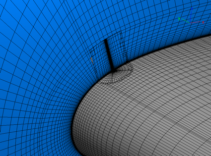
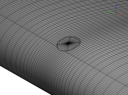
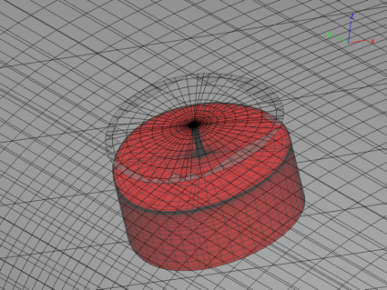
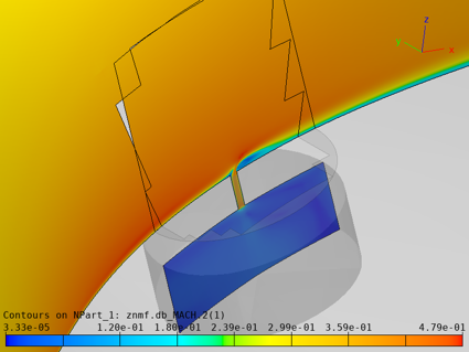
Chimera modelling of a ZNMF actuator on a wing
Preliminary steady CFD simulation performed with NSMB solver